There are many ways to connect your solar system. Some of the connection types only suit a particular type of solar system (grid or off-grid) you planned to use. While some can be used in any type of solar system. Also, there are many ways to carry out the wiring. Most times, it all depends on the solar PV system components you might wish to add or exclude. For example, a wiring design for a solar system where both batteries and generators are used as backup will differ a little from the one that uses only battery as backup. The same applies to grid connected systems, as there are different utility metering types, depending on the local utility requirement for solar projects in your area. In this article, you will learn the different solar PV connection types and categories, how to do the wiring and alternatives to AC load separation.

Schematic/Energy Flow Diagram of a Typical Solar PV System
In a typical solar system, the solar array captures energy from sunlight in form of DC and then transfer it to a charge controller. The charge controller uses this DC current to charge the batteries bank and also ensures that the required charging current and voltage of the battery is maintained. DC loads (if any) draw DC directly from the charge controller. The inverter usually has a connection terminal (positive and negative) to the batteries bank, from where it draws the DC stored in the batteries and then converts the DC to AC. Also, the inverter has AC output terminals (positive and negative) where the AC loads are connected. So the AC from the inverter now powers these connected AC loads.
The inverter also has AC input terminals (positive, negative and neutral) for connecting to the grid (mains) from which the battery can also be charged, although this optional, depending on the type of solar system and connection you wish to use. This is how a typical solar system works.
Below is a schematic diagram of a typical standalone solar PV system, with both AC and DC load, and batteries as backup. The arrows show the direction of power flow in the system.

Different Categories of Solar PV Connection/Configurations
The 5 main categories of solar PV connection include:
- Feed-in-Tariff (FIT) Connection
- Net-Metering/Net Billing Connection
- Net-Zero Electricity Connection
- Self-Use Only Connection
- Off-Grid Solar PV System Connection
Note that all these types of solar PV connection might be available in your locality. So you need to contact the utility service centre in your locality to know the types of solar PV connections they support and their requirements.
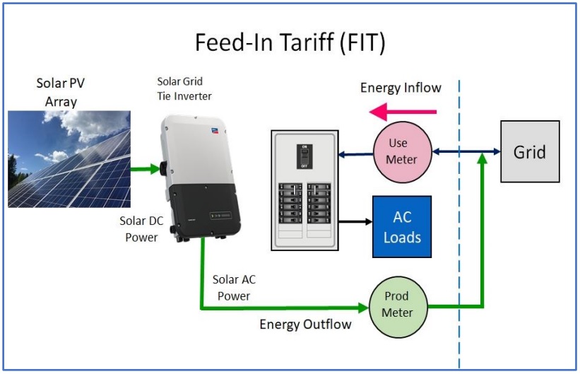
Feed-in-Tariff (FIT) Connection
For this type of solar PV connection, PV generated electrical energy during daytime flows directly into the grid, while the electrical energy for your home is drawn from the grid. So what this means is that you sell your PV generated electrical energy into the grid and then purchase all required electrical energy from the grid.
This type of connection requires two utility meters. One of the meters will measure the PV generated electrical energy you deliver to the grid, while the second meter will measure the amount of electrical energy you purchase from the grid. But note that for FIT PV connection, the electrical energy purchase rates and the energy credit (energy from your PV system) rates differ. Energy outflows from your PV system to the grid is credited at a lower value than energy inflows from the grid to your home.
Net-Metering/Net Billing Connections
For Net-Metering or Net Billing solar PV connections, your solar system delivers electrical energy to both your home and the grid. A higher preference is given to your home AC load energy demand, then excess energy generated by your solar PV system now flows to the grid. Whenever there is high energy demand by your home AC load than your PV system could generate, the excess needed energy flows from the grid to your home.
A special single utility meter measures both energy inflow from the grid and energy outflow to the grid. The billing is based on energy inflow from the grid to your home MINUS energy outflow from your solar PV system to the grid.
Net-metering connection type can also work with a multi-tiered rate structure. To earn higher returns on your solar PV investment, you need to design and size your PV system in such a way that electrical energy consumption from higher priced tiers are reduced or avoided as much as possible.
Also note that in net-billing connection type, energy inflows and outflows are valued at different energy rates, with energy outflows to the grid credited at a lower rate. This is the main difference between net-metering and net-billing solar PV connection types.

Net-metering configuration can be designed to have backup batteries and even backup generator using a bi-modal inverter, a charge controller and an essential panel for essential loads as shown below.

Net-Zero Electricity Connection
The net-zero solar PV connection works in similar way as net-metering, but has one major restriction. The restriction in net-zero connection, done by the utility centre is that the total energy outflow from your solar PV system to the grid MUST BE LESS THAN OR EQUAL TO the total energy inflow from the grid to your home over a period of 365 days. This restriction gave rise to the name “net-zero connection”.

Self-Use Grid Connection
For self-use grid connection type, there is no energy outflow from your solar PV system to the grid at any time. All solar PV generated electricity must be consumed by your home. But in times of inadequate energy generation capacity from your solar PV system (usually at night or when there is no sunlight), energy can be drawn from the grid to power your house AC loads.
An on-site PV battery is needed to store excess energy generated by your solar PV system during the day for later use. A solar PV inverter that can generate AC in parallel with the grid, using solar PV energy and/or energy stored in the batteries. You also need a self-use controller that will ensure that there is no energy outflow from your solar PV system to the grid, even when the battery is fully charged and excess PV energy is available. Some solar inverters can do this task.
Also, a charge controller is required to regulate the energy flow into the batteries from the solar PV array, and to ensure that energy does not flow the other way round (from the batteries to the solar array).

Off-Grid Solar PV System Connection
The off-grid solar PV connection type is very similar to the self-use grid connection type. But the difference is that the off-grid connection type is a standalone system with no connection to the grid (both for energy inflow and outflow). A battery is required to store excess solar PV energy generated during the day for later use.
A generator can also be incorporated as additional backup, especially in times of low or now sunlight (when there is very low energy generation rate by the solar PV array). A solar PV inverter-charger that can generate AC from the PV array, batteries bank, and also charge the batteries bank using the AC power from the backup generator while still powering your connected AC loads, especially in times of insufficient solar PV energy generation.

Check:
- Solution to All Solar PV Systems Installation Calculations
- 5 Best Ways to Make Money from Solar Energy Sector
Essential Parts of a Solar Power Inverter
One of the essential components of any solar PV system is the power inverter because it is the coordinating house of the solar system. In order to make a proper wiring of any solar PV system, you need to understand some of the essential parts of an inverter, especially the connection terminals.
A typical inverter system has 3 main connection terminals:
- Battery Connection Terminals
- AC Input Terminals
- AC Output Terminals
Battery Connection Terminals
This is a 2-wire DC terminal, usually red (positive) and black (negative) through which the inverter is connected to the battery. When the inverter is on standalone mode, these wire terminals supplies the DC power stored in the battery to the inverter, which the inverter then converts to AC power and then supplies to the AC loads connected to it. Also, when there is power in the AC utility mains (if connected to the inverter), the inverter charges the batteries through these 2 terminals.
Make sure that the total (effective) voltage of your batteries bank has the same value as your inverter system rated voltage. The inverter system rated voltage is usually in multiples of twelve. For example: 12V, 24V, 36V, 48V, etc. inverters. So if you are using a 24V inverter, then the total (effective) voltage of your solar PV batteries bank must be 24V.
AC Input Terminals
This is a 3-wire AC terminal, usually red (live), black (neutral) and green/yellow (earth) through which AC utility mains power is supplied to the inverter. The live and neutral cables (plus the earth cable) that supply utility power to your AC appliances (usually from your distribution box or changeover switch as the case may be) are connected to these terminals.
AC Output Terminals
This is a 3-port (live, neutral and earth) terminal on the inverter where the AC loads are connected. Most times, only two (live and neutral) ports out of the three ports are used. If you wish to use, the earth port, simply link it to the earth port/terminal in your distribution box (although not usually necessary).
Other essential parts of a power inverter include: display screen (digital or analogue), normal/bypass mode switch, ON/OFF switch, battery electrolyte display switch (for tubular batteries, optional).
All the essential parts of a solar inverter is summarized in the image below.

Various Ways to Wire a Self-Use On-Grid Solar PV Connection Type/Inverter Wiring
There are many ways to do the wiring for a self-use grid solar PV configuration. Most times the wiring method to use depends on the solar system components you wish to add or remove. For example, backup batteries and generator. Here, we will consider the 3 most common wiring strategies.
How to Wire a Self-Use, On-Grid Solar PV System with Only Battery as Backup
First, make connections to the battery terminals (positive and negative) from the charge controller’s battery connection terminals (positive and negative, always specified on the body of the charge controller) to the connection terminals of the battery or batteries bank. Next, connect the solar array to the charge controller’s solar array connection terminals (positive and negative, also specified on the body of the charge controller). Then connect the inverter battery connection wires (positive and negative) to the battery terminals.
You will need two changeover switches. The first changeover switch will control the load connection (from the distribution box) to the inverter AC output. The second changeover switch will control the inverter AC input connection to the AC utility mains (grid) of your house. The second changeover switch is optional, as you can make a direct connection from the inverter AC input to the AC mains without a changeover.
The wiring diagram of a self-use grid solar PV system with only batteries as backup, including the earthing system is shown in the image below.

NOTE:
For a self-use grid solar PV system, do not connect the inverter battery terminal wires (positive and negative) directly to the charge controller. Doing so might damage the charge controller.
Also, make sure you do the charge controller to battery connection first before connecting the inverter to the battery or the solar array to the charge controller, to avoid damaging the charge controller.
Do you wish to learn the step by step guide for solar PV system design and installation? Then check out this eBook on Amazon: Complete Solar PV System Installation Guide. It contains DIY guides for installing grid and off-grid solar PV systems, how to build solar-powered electric cars and the various ways to make money from the solar energy sector.
See:
- Step by Step Guide for Converting Conventional Cars to Solar-Powered Electric Cars
- Best Ways to Protect your Solar System via Effective Earthing
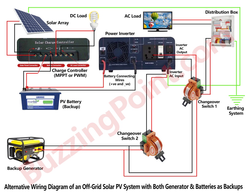
How to Wire a Self-Use, On-Grid Solar PV System with Both Generator & Battery as Backup
Here, the battery connection is the same as that of the self-use grid with only battery as backup explained above.
But you will need up to three changeover switches (minimum of 2 changeover switches). The first changeover switch will control the load connection (from the distribution box) to the inverter AC output. The second changeover switch will control the AC utility mains (grid) and the backup generator connection. While the third changeover switch will control the output of the second changeover and the inverter AC input connection. The third changeover switch is optional, as you can make a direct connection from the output of the second changeover to the inverter AC input without a changeover.
The wiring diagram of a self-use grid solar PV system with both generator and batteries as backup, with earthing system is shown in the image below.

NOTE:
Multiple changeovers help you to easily disengage any section of your wiring/connection in case of any fault occurrence, when troubleshooting a fault in the system or for convenience of use sake. For example, if you wish to switch from using the AC utility mains to the generator, you simply switch the second changeover from the AC utility mains section to the generator section. Similarly, if you wish to use only your PV energy to power your appliances without the aid of the AC utility mains or the backup generator (that is as standalone solar system), you simply disengage the third changeover from both the AC utility mains section and the backup generator section (usually by placing the control swing at the centre, thereby opening the circuit).
Also note that in a self-use grid solar PV configuration, the solar inverter (especially the bi-modal types) usually has an automatic transfer switch (ATS) that takes care of the switching the AC loads from the utility mains to the backup batteries (standalone) when there is power outage from the utility mains, and vice versa when power is restored in the AC utility mains. So you don’t need an external ATS for your solar PV system if your inverter already has this feature. You can check the inverter manual to confirm if it has this ATS feature.
Off-Grid Solar PV System Wiring Guide/Inverter Wiring
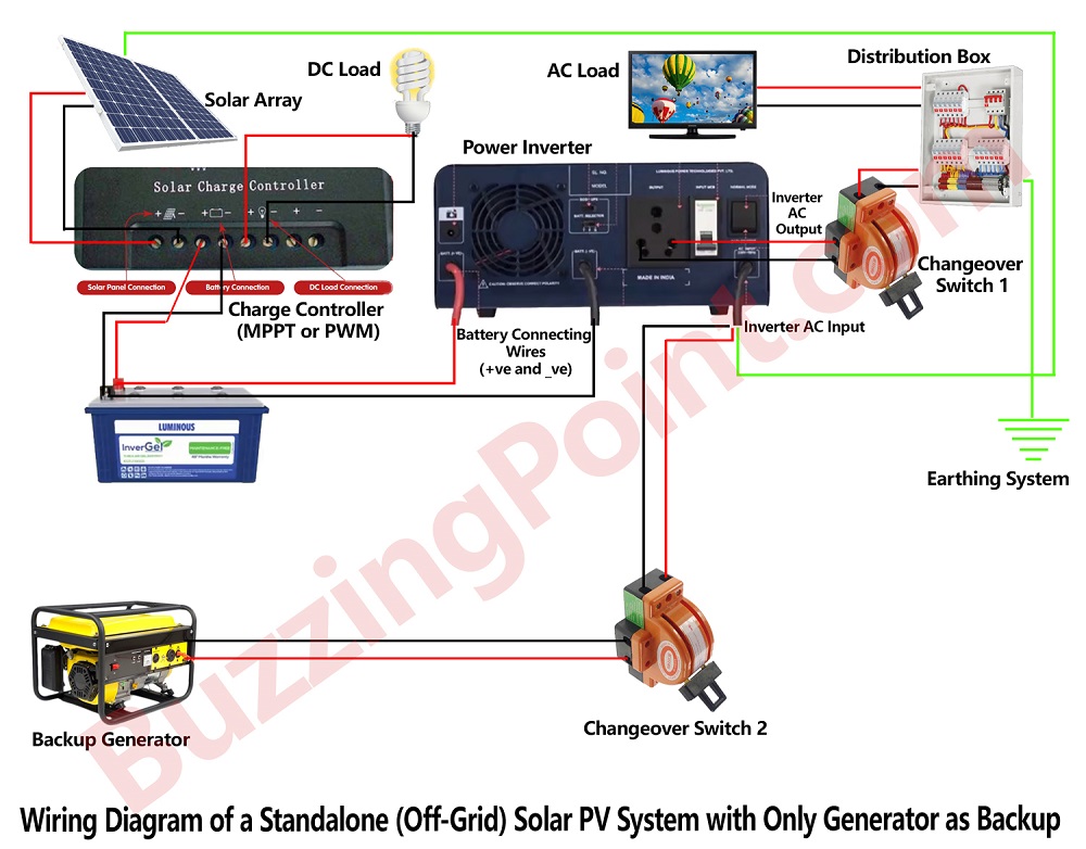
How to Wire an Off-Grid (Standalone) Solar PV System with Both Generator and Battery as Backup
To wire a standalone (off-grid) PV solar system, you don’t need any connection to the grid (utility mains). You can use both battery and generator as backup, so that the generator can function as the utility mains (grid) to the standalone PV system in periods or low sunlight. This is to ensure that the battery will not discharge below the recommended or permissible discharge level. You can convert any of the above wiring scenario (with battery as backup or with both battery and generator as backup) to an off-grid solar PV system by simply disconnecting the solar PV system from the grid (utility mains).
Here, you will need two changeover switches. The first changeover switch will control the load connection (from the distribution box) to the inverter AC output. The second changeover switch will control the inverter AC input connection to the backup generator.
The wiring diagram of a standalone (off-grid) solar PV system with both generator and battery as backup, including the earthing system is shown in the image below.
Alternative Ways to Connect your Solar System if You Don’t Want to Run Load Separation
Most times, you might have home appliances (like air conditioners, pressing iron, electric cooker, etc.) or even industrial machines or appliances which draw high current. If the rating of your inverter is not high enough to withstand such high currents, you should never power these heavy appliances with your Solar PV system.
The best alternative is to run load separation, such that these heavy appliances will only powered when there is power from the utility mains or maybe when you ON a suitable generator, but not when you are using your solar PV system o standalone mode.
Another alternative to running load separation in such situations is to adjust your solar PV system connection/wiring as shown in the wiring diagrams below.
For Self-Use, On-Grid Solar PV System with only Battery as Backup

For Self-Use, On-Grid Solar PV System with both Battery and Generator as Backups

For Self-Use, Off-Grid Solar PV System with both Batteries and Generator as Backups
With any of these solar PV system wiring styles, you can then manually switch to UTILITY MAINS ONLY mode or GENERATOR MODE ONLY when you want to use these high current-consuming electrical appliances. Thereby, saving your solar PV system (especially your inverter and batteries) from being damaged by over-current.
Conclusion
You have learnt the various electrical configurations for your solar PV system and how to wire your solar PV systems with changeover switches, especially the self-use grid and the off-grid solar system configurations. Feel free to try out these tips.
Did you find any section of this article confusing? Drop your questions in the comment section below. Don’t forget to subscribe to our blog via email to stay up to date with our upcoming tutorial article. Share this article with your social media friends by clicking a share button. Enjoy!